
iGuard User Manual
iGuard Brochure
- Download in PDF Format
iServerExpress
- iServerExpress.msi (1.0.46)
API Software Development Kit (SDK)
(LM520 series only)
Available upon request.
Employee Import Utility
iGuard Connection Diagram
iServer2
Remote door access
The Remote Door Access is used to unlock the door in an easy way.
That is a fast way to unlock the door in the computer without tedious procedure. You can unlock the door by double click the icon in the system tray.
Please click here to download the utility.
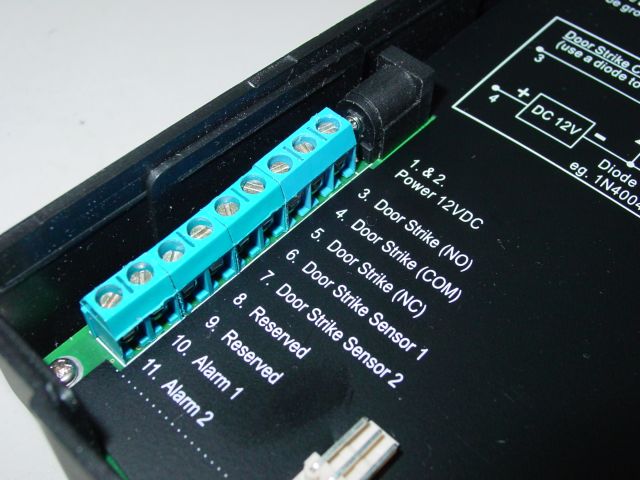
iGuard Connection
iGuard provides easy-access terminals for connections to external controls, including Door Strikes, Door Sensor, Door Open Switch, and External Alarm.
Power (12V DC) Power Plug
The power requirement is 12V DC, 600mA. Since most of the door strikes require the same 12V DC power supply, iGuard may share the same power supply with the door strike.
Door Strike (Optional)
Terminals #3-5 (3-4 Normal Open, 4-5 Normal Close). These terminals are connected directly to the internal relay, rating at 12V / 5A. If the door strike is within this current limit, it can be directly connected to these terminals. If the system is used solely for Time Attendance System, these terminals can be left open.
Door Sensor (Optional)
Terminals #6-7. It provides iGuard the current status of the door (open / close). If the door is left open for over 10 seconds, iGuard will generate beep sounds to alert the people.
Open Door Switch (Optional)
Terminals #8-9. An optional door switch can be connected to these terminals. It is used to open the door remotely, such as opening the door from the inside of the business premises, or from the reception area.
External Alarm (Optional)
Terminals #10-11. This is used for optional external alarm. If the case of the device is forced open during operation (such as a break-in), an internal sensor will trigger this connection, and it will sound the external alarm.


External Controls
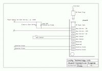
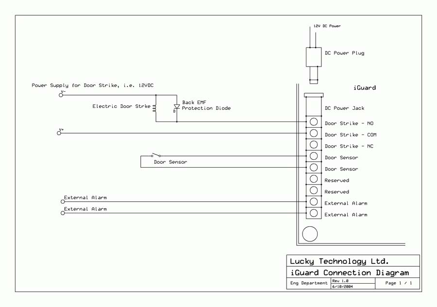
A Typical Door Connection